Solder your LiV board
We assume that you know how to solder. If you don’t, you can find a tutorial on the web. We recommend you to purchase an inexpensive electronics kit and develop your soldering skills before you start assembling LiV.
We are not responsible for any accidents (electric shocks, fires, injuries, etc... ) that might happen to you during the assembly of this kit. Everything you do while assembling the kit is at your own risks.
Please take the time to read and understand the following guide before you start soldering your LiV board. If there are things that are not clear or if you spot errors or missing pieces of info, please let us know at: support AT firstcypress dot com.
The next picture shows the component side of LiV Board for Raspberry Pi model 3, 2 and B+. The numbers associated with the different components indicate the soldering order. Those numbers also correspond to the step number in the following soldering guide.
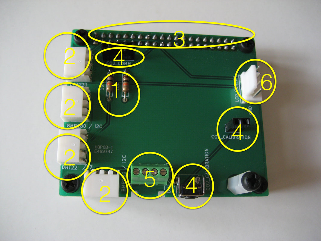
Step 1
Populate the component side of the board with the two resistors (both 10K). These are pull-up resistors connecting pin 1 and pin 2 of DHT22 or DHT11 sensors.
Populate the component side of the board with the two resistors (both 10K). These are pull-up resistors connecting pin 1 and pin 2 of DHT22 or DHT11 sensors.
Step 2
Solder 4 pin right angle female connectors. There are four of them: one for DS3231 RTC module (I2C port operating at 5V), two ports for BMP180 air pressure sensor (I2C port operating at 3.3V) and one ports for DHT22 temperature/humidity sensors.
Solder 4 pin right angle female connectors. There are four of them: one for DS3231 RTC module (I2C port operating at 5V), two ports for BMP180 air pressure sensor (I2C port operating at 3.3V) and one ports for DHT22 temperature/humidity sensors.
Step 3
On the back side of the board - solder the 26 pin female connector or 40 pin female connector that plugs into your Raspberry Pi model B or model 2 or B+ respectively. Be careful when you solder so you don’t create shorts between pins.
On the back side of the board - solder the 26 pin female connector or 40 pin female connector that plugs into your Raspberry Pi model B or model 2 or B+ respectively. Be careful when you solder so you don’t create shorts between pins.
Step 4
This applies if you have an Expert kit with the K30 CO2 sensor in it: On the component side of the board - solder the 4 and 2 pin female connectors and the CO2 calibration switch. If you don’t have a CO2 sensor, go to step 5.
This applies if you have an Expert kit with the K30 CO2 sensor in it: On the component side of the board - solder the 4 and 2 pin female connectors and the CO2 calibration switch. If you don’t have a CO2 sensor, go to step 5.
Step 5
Solder green connector. This is the second DHT22 port close to the CO2 calibration switch.
Solder green connector. This is the second DHT22 port close to the CO2 calibration switch.
Step 6
On the component side of the board - solder the LCD screen connector (SCREEN). This is an I2C port operating at 5V.
On the component side of the board - solder the LCD screen connector (SCREEN). This is an I2C port operating at 5V.
We are testing all the sensors we ship, so we are soldering the connectors on the BMP 180 and K30 sensors. If you wish to solder the connectors yourself, please let us know and we will send you the sensors and connectors so you can solder them yourself. Here are the instructions:
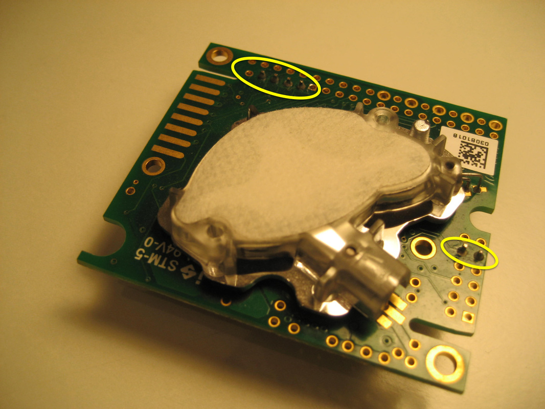
Solder the four pin male connector on the BMP180 air pressure sensor. Solder four pin male connector and two pin male connector on the K30 CO2 sensor. The DHT22 temperature sensor does not require any connector soldered. Please refer to the next pictures that shows the connectors on the air pressure and CO2 sensor.
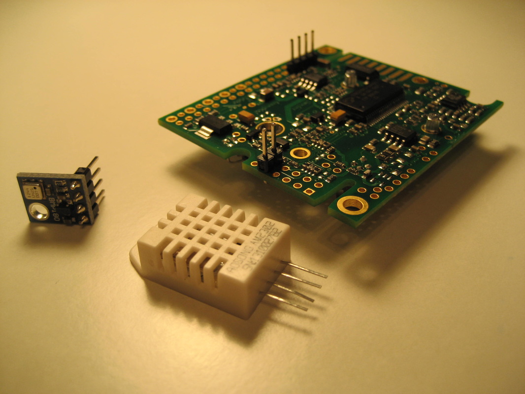
Please pay extra attention when soldering the connectors on the K30 sensor. You should use a fine iron tip so that you will not short pins. This is the most expensive part in your kit. We can not replace sensors damaged by incorrect soldering.
Step 7
Perform visual inspection on your board to make sure your soldering points look OK and there are no shorts between them. Use a meter to check that there are no shorts between GND and 3.3V PWR and 5V PWR. You can do this directly on the Raspberry Pi connector that you soldered at step 3.
Perform visual inspection on your board to make sure your soldering points look OK and there are no shorts between them. Use a meter to check that there are no shorts between GND and 3.3V PWR and 5V PWR. You can do this directly on the Raspberry Pi connector that you soldered at step 3.
